Adding Cubic Curve Segments
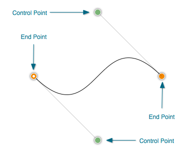
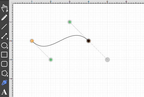
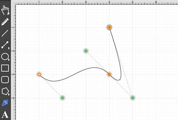
A Cubic Curve is a line segment with two end points and two control points that determine the exact curve to be drawn. The image below illustrates an example of a cubic curve.
Two core gestures are available when creating path segments. A Single Click will add just an end point and Click/Drag combination will add an end point with a corresponding control point. Since a cubic curve contains two end points and two control points, a cubic curve can only be added by performing a Click/Drag combination at one point and then by performing a Click or Click/Drag combination at another point.
For example, complete the following steps to draw a path like the one displayed in the example above:
-
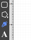
Select the Path Tool.
-
Click on a desired starting point on the drawing canvas and drag to another location to establish the first control point. The orange handle with the white dot signifies the starting point of the path. The gray circle or “phantom” control point will turn into a control point when a curve segment is drawn.
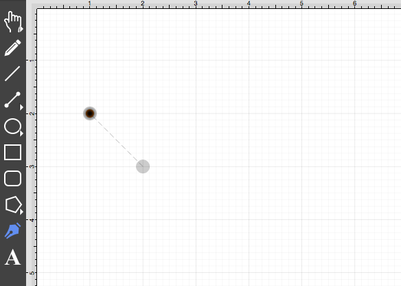
A control point is displayed in gray when it has not been used and is referred to as a “phantom” control point. This characteristic provides a hint to the TouchDraw application that it should function as a control point in scenarios where the next drawn segment is a curve. The control point is ignored when a straight line segment is added.
-
Next, click on the point within the drawing canvas where the segment end point will be and then drag the “phantom” control point outward toward the right and bottom of the drawing canvas to create the desired curve. A real control point will be placed exactly opposite (relative to the endpoint) from the current location of the “phantom” control point.
Performing an Option/Click combination on any location in the drawing canvas alters the position of the “phantom” control point to the selected location. Refer to the Path Tool section to learn more about this action.
-
Since a path is being created rather than a shape, a Double Click must be performed on the drawing to inform TouchDraw of the completed path.
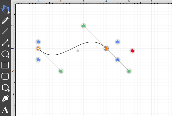
The handles for curve control points are green. The color and look of the control points are an indicator of how they relate to the selected shape. Refer to the handles reference page to learn about the types of handles.
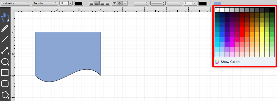
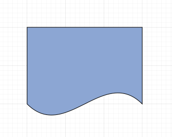
The next step is to create a shape like the one shown below.
-
Select the Path Tool.
-
Repeat the steps above to create curve on the bottom of the shape as shown below.
-
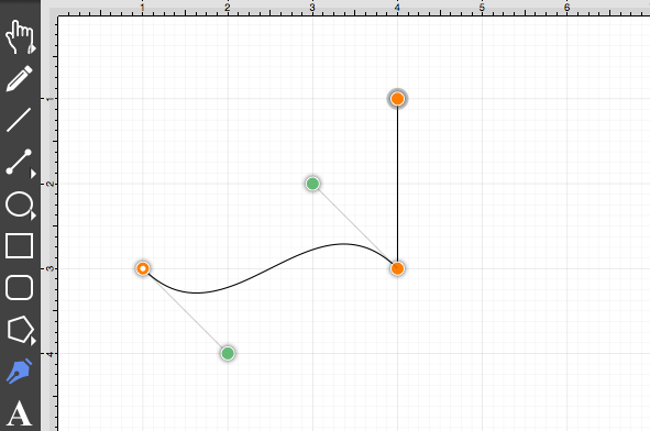
Next, draw the edge on the right hand side of the shape. If a control point exists and a Click is completed to add a single endpoint, TouchDraw will use the “phantom” control point to create a curve. Hold the Shift Key down while performing the Click action on the end point location to inform TouchDraw that a straight line should be added. The following screenshot illustrate what happens when the Shift Key is not used:
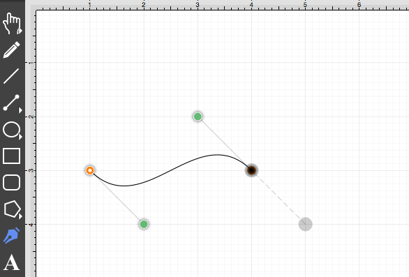
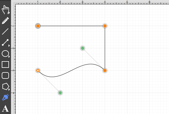
The following screenshot illustrates what happens when the Shift Key is held as the Click action is completed.
-
Next, click in the upper left hand corner where the next end point should be.
-
Finally, to close the path and to create a shape, Click on the start point (the orange handle with a white dot).
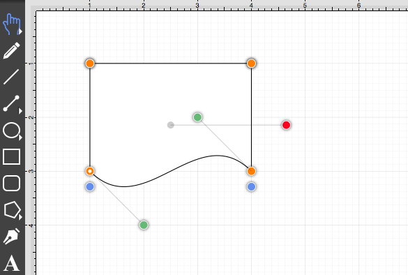
-
To set the color, click on the fill button located on the main toolbar and choose light blue. Refer to the Handling Colors portion of the documentation to learn more about using colors.